52 Results
View results:
Sort by:

Everything is online. The same is true for the Dlubal licenses for RFEM 6, RSTAB 9, and RSECTION. This article contains information about using and managing online licenses, reserving licenses, checking the license validity, and moving authorizations between the licenses.
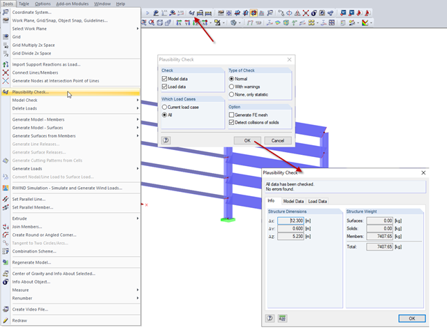
In RFEM and RSTAB, you can check the plausibility of entries before you start the calculation. This is done using "Tools" → "Check Plausibility ..." or the corresponding button in the toolbar. There are three different types of checks available.
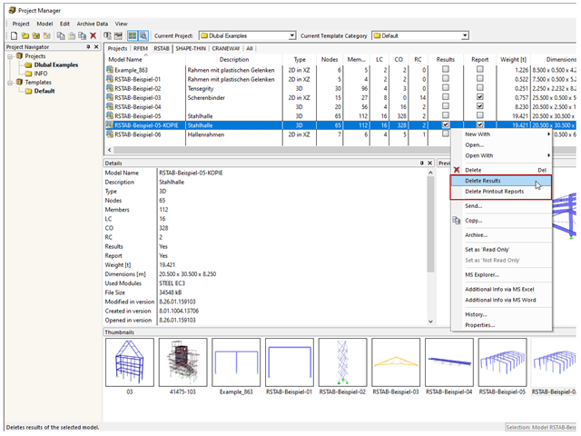
In rare cases, it may happen that an RFEM or RSTAB file cannot be opened. These files contain mostly results and report data.

In RF-/STEEL EC3, sets of members are calculated according to the General Method (EN 1993-1-1, Cl. 6.3.4) together with the stability analysis. To do this, it is necessary to determine the correct support conditions for the equivalent structure with four degrees of freedom. In most 3D models today, you can quickly lose track of the location of a set of members in the system.

In CRANEWAY, the action of a rail as "statically effective" or "statically ineffective" is defined under "Rail‑Flange Connection" in the Details dialog box. This setting controls the calculation of the load introduction length according to EN 1993-6, Tab. 5.1.
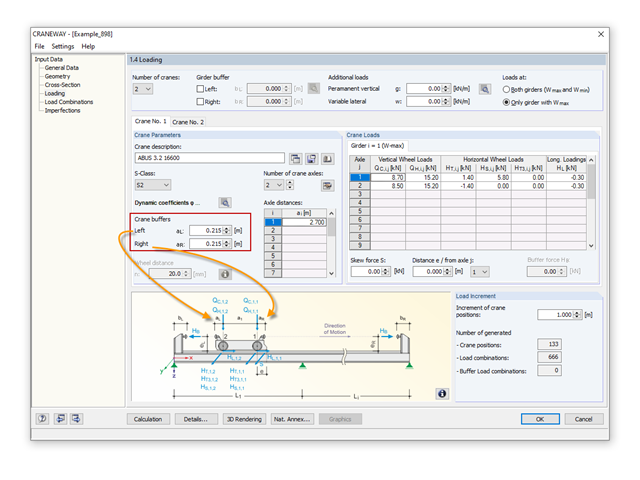
In the event of converting or extending a hall, the building owner may want to add a second or third crane to an existing crane runway. Since the original design usually does not consider other cranes, a common solution is to design a minimum distance between the cranes. This is done via the crane technology settings.

In the age of BIM, data exchange between the various disciplines of structural engineering is becoming increasingly important. Since each software has its own specifications with regard to the description of cross-sections and materials, RFEM and RSTAB offer a conversion table (mapping file).

Supports contributing to a load reduction only under compression or tension can be defined as nonlinear supports in RFEM and RSTAB. It is not always easy for the user to select the correct nonlinearity for "failure under tension" or "failure under compression".

The automatic creation of combinations in RFEM and RSTAB with the "EN 1990 + EN 1991‑3; Cranes" option allows you to design crane runway beams as well as support loads on the rest of the structure.

You can color the surfaces in the direction of the local z‑axis using the indicated option in the Display Navigator. By default, the side lying in the negative z-direction is colored red and the side lying in the positive z-direction is colored blue.
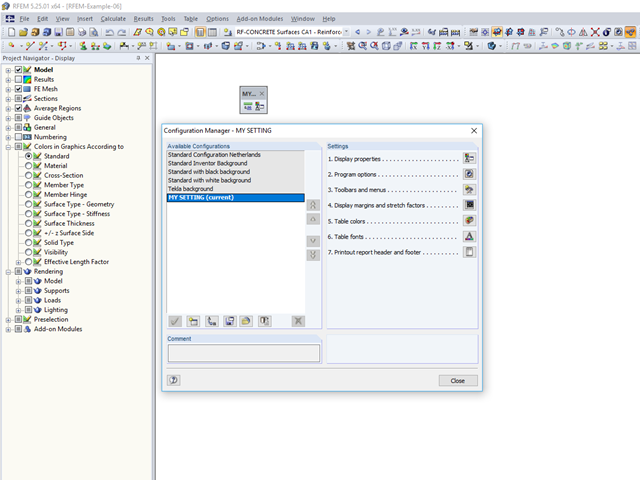
An individual user‑defined workspace can increase your productivity and make your daily work easier. This is why many users take the opportunity to adjust the toolbars in RFEM and RSTAB and to create their own toolbars containing the most frequently used commands.

You can use the "Free Circular Load" option in RFEM to apply a partial uplift force to a cone‑shaped floor slab. It can be defined as linearly variable. The definition of center C and the outer boundary R can be specified easily, using the select function.
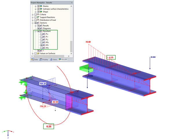
For control purposes, it is possible to display the resulting internal force in sections in RFEM. To illustrate this, the bending moment was selected in this example.
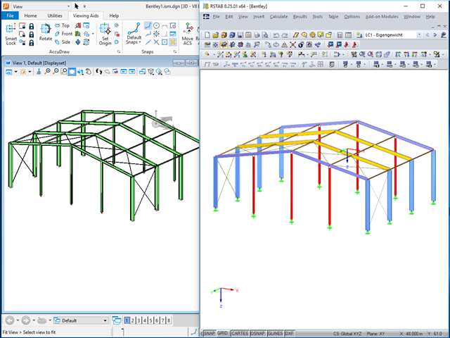
The ISM file (ISM = Integrated Structural Modeling) in RFEM and RSTAB provides an interesting option for exchanging data. If you export a model to this data format, you can view and analyze it with the free ISM viewer from Bentley.
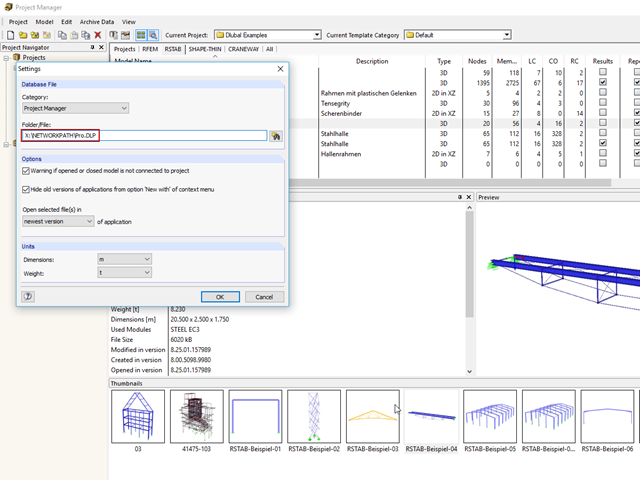
Due to rapid development in the IT sector, including structural design, the trend is towards a global model. Large projects are rarely carried out by a single engineer. Unified project management is the key to successful work in major projects.
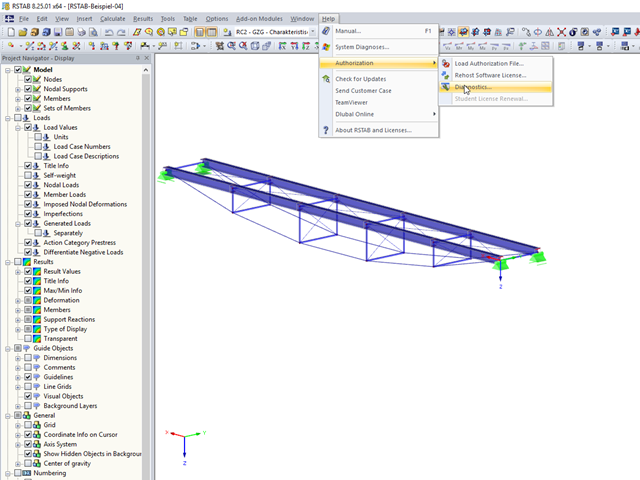
In RFEM 5 and RSTAB 8, you can view detailed information on the currently used license and installed dongle driver. In case of any problems with the license, you can send the created text file to the Dlubal Software hotline, which allows us to provide you with a fast and efficient analysis. To create the file, select "Help" → "Authorization" → "Diagnostics".
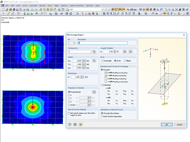
RFEM 5 provides the option to define a smoothing area in the "Results" → "New Average Region" menu. You can choose a rectangular, circular, or elliptical shape. With this tool you can, for example, "smooth" singularities due to nodal loads in a desired averaged region.
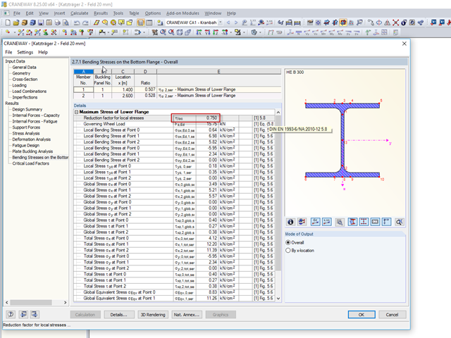
In CRANEWAY 8, you can design suspension cranes according to EN 1993-6. For the design, it is necessary to determine the local bending stresses in the lower flange due to wheel loads according to EN 1993‑6, Clause 5.8.
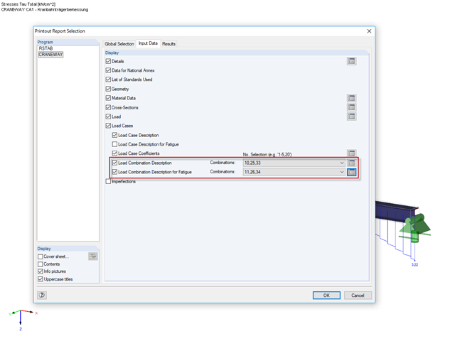
The selected increment of the load positions automatically increases the generated load combinations.
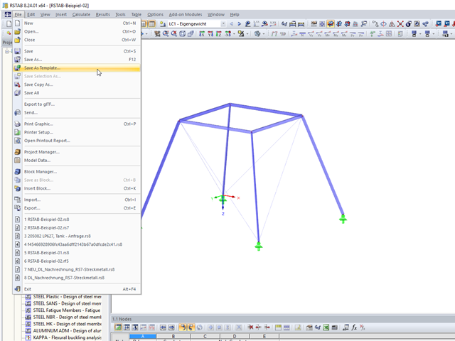
These days, it is common practice to use structural standard templates. Thus, only the basic structure has to be adjusted to the current project.

Closed circular cross-sections are ideal for welded truss structures. The architecture of such constructions is popular when designing transparent roofs. This article shows the special features of the connection design using hollow sections.
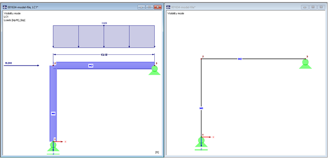
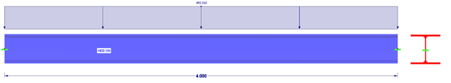
The beam is resting on the column, and the beam ends at the outer edge of the column. These requirements can be fulfilled easily in an architectural model with solids. In member analysis, simplified line models are used in which center lines meet in a common node. In this article, the influence of member eccentricities on the determination of internal forces is shown on three simple models.
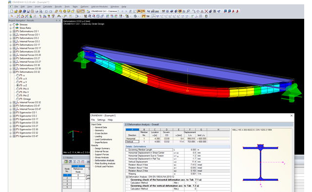
This article describes the different options for determining the allowable deformation of crane runway girders. Since multi-span beams and flexible lateral supports (sway bracing) are used in practice, this article will show how to select the correct method.
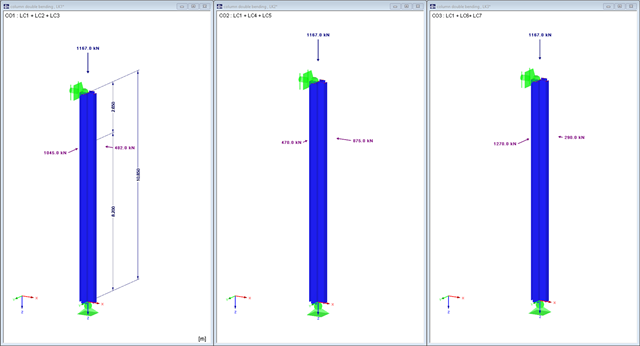
This example will show what you should consider when you perform column design for bending and compression with regard to the internal forces from load combinations and result combinations.

For crane runways with large spans, the horizontal load from skewing is often relevant for the design. This article describes the origin of these forces and the correct input in CRANEWAY. The practical implementation and the theoretical background are discussed.
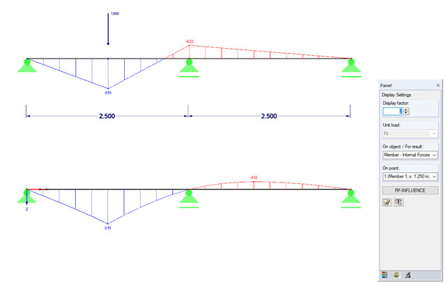
Influence lines are less important nowadays due to fast computer systems. However, it might be an advantage to use influence lines in the phase of preliminary design, as well as in the actual creation of the structural designs. With the RF-INFLUENCE add-on module, influence lines and influence surfaces can be generated and evaluated easily due to a fixed internal force. This technical article describes, with a simple example, the basics of determining and evaluating influence lines.
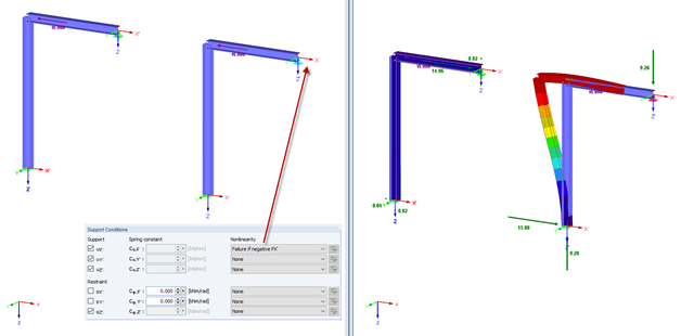
In practice, an engineer often faces the task of representing the support conditions as close to the reality as possible in order to be able to analyze the deformations and internal forces of the structure subjected to their influence and to enable construction that is as cost efficient as possible. RFEM and RSTAB provide numerous options for defining nonlinear nodal supports. This second part describes the options for creating a nonlinear support for a restraint and provides a simple example. For a better understanding, the result is always compared to a linearly defined support.
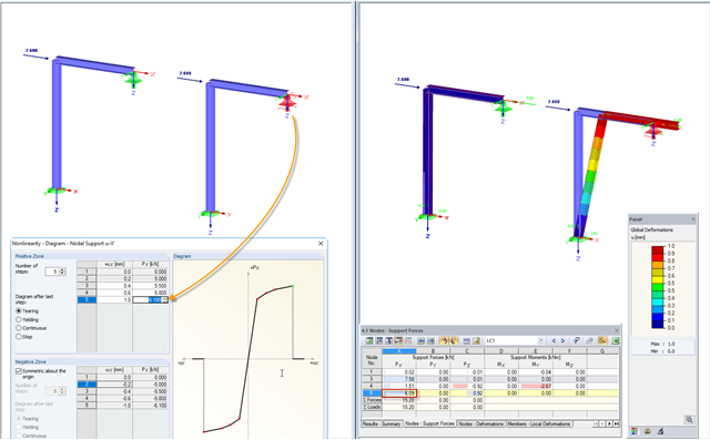
RFEM and RSTAB provide numerous options for nonlinear definitions of nodal supports. With regard to an earlier article, further possibilities of the nonlinear support design for a movable support are shown in a simple example in this article. For a better understanding, the result is always compared to a linearly defined support.
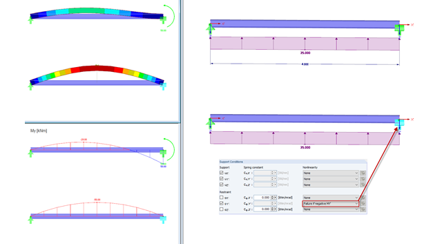
In practice, an engineer often faces the task of representing the support conditions as close to the reality as possible in order to be able to analyze the deformations and internal forces of the structure subjected to their influence and to enable construction that is as cost-effective as possible. RFEM and RSTAB provide numerous options for defining nonlinear nodal supports. The first section of my article describes the options for creating a nonlinear free support and provides a simple example. For a better understanding, the result is always compared to a linearly defined support.
Building in existing structures has been always an area of expertise of engineers. Often, additional loads have to be added to existing buildings. In this case, steel girders with end plates and dowel connections are frequently used.